Sagnac, Michelson & Co
Relativity to "touch"
RuedigerRodloff
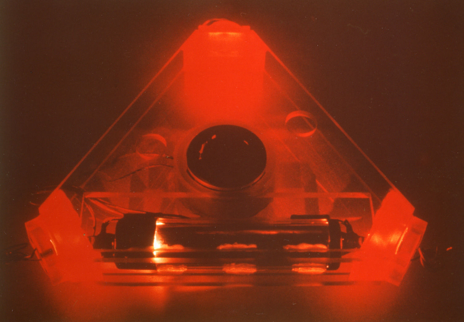
Background image - DLR - Experimental Laser Gyro - ELSY
The Sagnac experiment - a success story
The Sagnac effect forms the physical basis of the optical gyroscopes, which have partially replaced the classic mechanical gyroscope in the form of glass fiber or laser gyroscopes in autonomous navigation. In addition, the Sagnac interferometer can be seen as a counterpart to the Michelson interferometer and together with it forms the basis of the theory of relativity.

Georges Sagnac, 14.10. 1869 (Perigeux) - 26.2. 1928
Sagnac studied 1890 to 1893 physics at theEcole Normal Superieure and also at theSorbonne with a licentiate degree in physics. His teachers includedMarcel Brillouin,Gabriel Lippmann,Edmond Bouty andJules Violet. After that he was a preparator in Bouty's physics lab. In 1900 he received his doctorate with a dissertation on X-rays (De l'optique des rayons de Röntgen et des rayons secondaires qui en dérivent). WithPierre Curie he demonstrated photoelectrons when irradiated with X-rays. From 1900 he was maître de conférences at theUniversity of Lille and from 1904 chargé de cours at the Sorbonne, from 1912 as adjointe professor. In 1920 he became maître de conférences for theoretical physics and celestial mechanics to the professorsAime Cotton and thenAnatole Leduc, who held the corresponding chair, took the lectures (they continued to teach general physics). In 1926 he retired and received the title of honorary professor.
Starting from a light source (nowadays a laser), a beam of light hits a beam splitter; the partial beams pass through the mirror arrangement in the opposite direction and are decoupled again after one revolution at the beam splitter and become oneinterference fringe pattern superimposed.
Important for practical use: the interference fringe pattern shifts proportionally to the rotation speed and remains shifted by a fixed amount at constant rotational speed, - in contrast tolaser gyro in which the interference fringes run continuously at a constant rotation rate!
This introduction does not deal with the technical realization of optical gyroscopes, but with some questions that are of fundamental importance for the application of the Sagnac effect, in the literature, however, mostly come up short:
- What influence does the signal speed have?
Or to put it another way: light propagates more slowly in a glass fiber than in a vacuum or in air. Does this have an influence on the measuring effect?
In another chapter, the question will be addressed as to whether the Sagnac effect is a relativistic effect, or whether it must be described and understood using the means of classical (pre-relativistic) physics?
These topics will occupy us in the next chapters. As an introduction, however, we will first focus on a purely classical description - adopt Georges Sagnac's point of view, so to speak:
Sagnac was interested in how light behaves in rotating systems; his experiments can definitely be seen as a counterpart to the Michelson experiments, who were interested in the influence of a uniform, straight-line speed on the propagation of light.
Seen in context, the results of both experiments are an excellent indication of the correctness of the theory of relativity - but more on that later!
Even if the opponents of the theory of relativity claim the opposite: In the chapter "Runtime Effects in Relatively Moving Systems" I will show you how the results of Michelson and Sagnac can be easily "reconciled" with each other and how the knowledge can be derived from this in an almost playful way that the Sagnac effect is a purely relativistic effect!
Here the Sketch by Georges Sagnac of the "Ring" interferometer he used:

In fairness it should be mentioned that a similar experiment was carried out by Franz Harress between 1909 and 1911 - well before Sagnac. However, his measurement results were not correctly interpreted until 1920 by Max von Laue. (more)
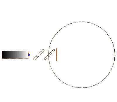
The experimental setup that Sagnac used for his investigations - especially the accompanying sketch (above) - is somewhat confusing; So here is a (hopefully) somewhat simpler outline:

Here is a slightly different representation with a circular light guide loop - it is easier to calculate in this representation afterwards !!!

In this arrangement, the light (represented here by a small blue sphere) first passes through a partially transparent mirror and then hits a beam splitter; There it is divided (yellow and green ball) runs through the circular light guide system, is decoupled again after one revolution and finally superimposed on the first partially transparent mirror.
If everything is set correctly, the two light beams will follow exactly the same path after one revolution.
We are now interested in the question of whether a rotary movement causes a change in the path between the light wave trains rotating in opposite directions.
The animation could look like this:
To anticipate it right away - this time the animation, or the expectation of the physicists, agrees with the result of the experiment!
You remember? A similar animation failed us once before with the Michelson interferometer!
To make things a little easier for the calculation, let's first assume that the light guide system (light guide system!) is circular and the pivot point is exactly in the center.
The device rotates with the angular velocity , has the radius r and the light guide system therefore has the peripheral speed:
In this ring-shaped light guide system we let a light wave run around once in the direction of rotation and once against the direction of rotation.

Light wave train in the direction of rotation

Light wave train against the direction of rotation
... and now the calculation is very similar to the Michelson interferometer: The light wave train runs through the ring-shaped light guide with the speed c. While the wave train encircles the fiber optic system once in the direction of rotation (sketch on the left), the fiber optic system has moved on by the distance v.dt+, i.e. it must cover the entire distance

return. This results in the transit time of the light wave train in the direction of rotation dt+ :

The arrangement moves in the opposite direction to the wave train running in the opposite direction (sketch on the right); during the circulation time dt- the optical fiber system has moved by the distance v . dt- moved; the entire path is shortened from L to:
From this follows for the propagation time of the light wave train in the opposite direction:


Already at this point the close relationship between the Michelson and the Sagnac interferometer becomes clear (at least from the point of view of classical physics!); the expressions for the travel times dt+ and dt- in the Sagnac interferometer and in the arm of the Michelson interferometer, which is parallel to the speed to be measured, are completely identical!
With the Michelson interferometer we had to add the two transit times (out and back) in order to be able to compare them with the transit time in the second perpendicular arm - with the Sagnac interferometer we can directly compare and form the transit times of the two wave trains circulating in opposite directions hence the difference:

with: and:


Interim remark!
You remember ? With the Michelson interferometer, we had to use a transit time difference of
getting ready. Since quaratic occurs, the Michelson interferometer is referred to as a 2nd order effect. In comparison, the Sagnac effect is a 1st order effect!
is a fairly small value and from the comparison of the runtime differences for the Sagnac and the Michelson interferometer it becomes clear where the problem lies in the evaluation of the measurement results with the MIchelson interferometer!
With c = 300,000 km/s (speed of light) and v = 30 km/s (speed of the earth on its orbit around the sun) this results
= 10 exp-4 !


To evaluate the transit time effect with the Sagnac interferometer, the procedure is very similar to that of the Michelson interferometer:
- After one revolution, the light wave trains are coupled out and superimposed on them; the resulting interference fringe pattern shows the transit time difference in the form of a travel or phase shift.
Considering and and results from the above relationship for the transit time difference Tsagnac :
If you now also consider the connection between the speed of light, frequency and wavelength , taken into account, then one obtains for the phase shift:
i.e. when the Sagnac interferometer is rotated, the fringe pattern shifts by the fixed value proportional to yaw rate .


For the "navigation experts" among you:
The Sagnac interferometer, e.g. in the form of a glass fiber gyro, provides information about therotation speed. If you atangle of rotationis interested, this signal still has to be integrated over time!
If you use the Sagnac effect in an optical ring resonator - the thing is then called"laser gyroscope" - then you get an output signal proportional to the angle of rotation, i.e. each passinginterference fringes corresponds to an angle increment - this is often confused in the introductory literature! (But the laser gyro is not our topic here.)
Let's calculate an example:
Area of the ring interferometer F = 1 sqm
Wavelength of the light used: = 633 nanometers = 0.633 x 10⁻⁶ m
Speed of light c = 3 x 10 +8 m/sec
Rotation speed = 1360 degrees/sec (almost 4 revolutions per second !)
... results in almost exactly 180 degrees for the phase shift, i.e. the interference fringe pattern shifts by half a fringe width from bright to dark.
For rotation speeds that would be of interest for navigation, e.g. the earth's rotation rate of 15 degrees/h, a phase shift of 8.75x10⁻⁵o degrees to be expected; i.e. for such applications the interferometer surface F would have to be made significantly larger, which should be possible with modern optical fibers wound on a spool.
Uff that was a bit "tedious", but actually trivial - right?
But what is really remarkable about this result is :
--> in contrast to the Michelson interferometer, the Sagnac interferometer does us the favor that the experiment exactly confirms our "trivial calculation"!
An obvious argument to explain the discrepancy in the results would be that the Sagnac experiment (rotation) is an accelerated movement, while the Michelson experiment is a non-accelerated, uniform movement. A. Sommerfeld comments on this (Preliminary on theoretical physics, vol. IV, p.67), "If one considers that the experiments (by Sagnac) are only about velocities v<<c and only about effects of the first order in v/c, one can simply calculate classically."
For the sake of completeness it must be mentioned that Michelson did in fact observe a small effect in his first experiments, which was however 20 times smaller than expected.
In the later countless repetitions of the experiment, this residual effect could be reduced further and further, so that it is probably just a measurement error. ( more)
But even if one assumes - like the critics of relativity - that it is not a question of a measurement error, then at least one has to explain why the measurement result deviates so significantly from the calculation.
I don't know how you are? - I have a very bad feeling looking at these results!
We calculated signal propagation times for both the Michelson experiment and the Sagnac experiment.
In the first case, the signal path was moved in a straight line and uniformly with the speed v, in the second case it was the peripheral speed v of a rotating system. In both cases it was a kind of "race" between the signal (=light wave train) and a moving target!
The calculations were almost identical in both cases. Nevertheless, the experimental results are as different as can be - in the first case azero result, in the second casecomplete agreement between calculation and experiment !
There is only one conclusion left: We have overlooked something fundamental in our calculations - becauseif our calculation does not agree with the result of the Michelson experiment, then the calculation for the Sagnac experiment must also be wrong, because our basic approach is exactly the same here!
I know - the opponents of the theory of relativity argue exactly the other way around, according to the motto: what leads to the correct result in the Sagnac experiment cannot be wrong in the Michelson experiment!(Click here for the critics of relativity.)
I think we have to completely reopen the whole topic and we should pay very close attention to the boundary conditions!
Please don't get me wrong: I have no interest in getting involved in the argument about the theory of relativity. I just want to provide a "clean" description of the Sagnac effect and examine some related questions that can hardly be answered with the traditional calculation presented so far:
For example, the Sagnac effect is:
- independent of the signal speed ?
and
- a purely relativistic effect?
In particular, the negative outcome of the Michelson experiment kept physicists very busy at the beginning of the last century and at led to a lot of "pseudo-explanations"!
In the next chapter (problem) we first want entirely from the point of view of pre-relativistic physics the examine the question of how to explain the different results of the Michelson and Sagnac experiments - which of course (!) does not work and in the following chapter (solution) we will finally clarify the matter.
So go!